| The
maximum permissible AC voltage that can be applied to
capacitors in sinusoidal waveform
applications, can be determined from the graphs in the
respective capacitor ranges.
However, where pulse conditions exists, the following procedure is to be observed to
ensure that the correct capacitor rating is selected for
a particular duty:
 Rated
voltage (Ur): The rated
voltage of a capacitor against a zero potential reference
point shall take into consideration that the dielectric
strenght of the capacitor film diminishes with rising
frequency. The calculation of the required rated voltage
of a capacitor must therefore allow for the correction
factor k; where k =
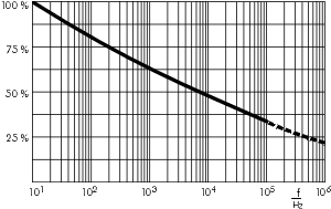
dielectric strength of the film at the frequency f in % is shown in graph 1. Rated
voltage (Ur): The rated
voltage of a capacitor against a zero potential reference
point shall take into consideration that the dielectric
strenght of the capacitor film diminishes with rising
frequency. The calculation of the required rated voltage
of a capacitor must therefore allow for the correction
factor k; where k =
dielectric strength of the film at the frequency f in % is shown in graph 1.
 |
|
Graph 1:
Dielectric strength of
Polypropylene film
as a factor of frequency
(general guide). |
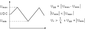
The calculation of the
required dielectric strength is shown in the following
example(Umin, Umax have
the same polarity).

Furthermore the rms
voltage derived from the peak to peak voltage shall not
be greater than the nominal AC voltage rating of the
capacitor to avoid the ionization inception level:
Urms < UAC rated.
 Maximum
current: The voltage gradient or rise time of
the pulse is taken as the reference point when
calculating the maximum current rating of the end
contacts. The maximum possible current load on the end
contacts is calculated by means of the voltage rise of
the pulse (pulse rise time F). Maximum
current: The voltage gradient or rise time of
the pulse is taken as the reference point when
calculating the maximum current rating of the end
contacts. The maximum possible current load on the end
contacts is calculated by means of the voltage rise of
the pulse (pulse rise time F).
Imax = F x C x 1.6
The data of the rated
pulse rise time Fr for pulses equal to the rated
rated voltage figure in the technical data of the
different types. With low voltage rise in operation (Upp) the permissible current load is calculated
as follows:

for example Ur = 63 V, Upp = 12 V, Fr = 50
V/µsec.
hence Fmax =  x 50 = 262.5
V/µsec. x 50 = 262.5
V/µsec.
When using maximum current
ratings, self-heating must be taken into account at
higher frequencies, and must not exceed 8 K.
 Dissipation
(heat losses): The heat dissipated by a
capacitor when stressed by non-sinusoidal voltages or
when under pulse conditions can be approximately
determined from the following formula: Dissipation
(heat losses): The heat dissipated by a
capacitor when stressed by non-sinusoidal voltages or
when under pulse conditions can be approximately
determined from the following formula:
| Pd |
= Urms2 x  C
x tan C
x tan where where |
| Pd |
= dissipation in
Watts (see table 1 for the max.W per K). |
| Urms |
= root mean
square value of the AC voltage share |
 |
= 2 x f,
where f is the repetition frequency of the pulse
waveform. x f,
where f is the repetition frequency of the pulse
waveform. |
| |
 C = capacitance in Farad C = capacitance in Farad |
tan |
= dissipation
factor corresponding to the frequency of the
steepest part of the pulse. |
pulse frequency = 
The temperature rise is as
follows:
Temperature rise in K =  (see table 1) (see table 1)
Printed circuit
module
PCM (in mm) |
Specific
dissipation in Watts per K
above the ambient temperature |
2.5
5
7.5
10
15
22.5
27.5
37.5 |
0.0025
0.004
0.006
0.0075
0.012
0.015
0.025
0.03 |
|
|
Table 1: The data is for
ordinary assembly and
ventilation conditions avoiding
radiant heat within the chassis
of the equipment. |
| |
| In
applications where reliability is critical, it is
recommended to measure the surface temperature of
the capacitor and to take into account that the
temperature within that capacitor will be
approximately 5 K above the case temperature. |
 Determining
the permissible AC voltage and AC current at given
frequencies. Determining
the permissible AC voltage and AC current at given
frequencies.
To determine the permissible AC voltage (sinusoidal) for
applications in a higher frequency spectrum, graphs
showing AC voltage derating with frequency are available
for the respective WIMA series. The diagrams refer to a
permissible self-heating of:
 < 10 K. < 10 K.
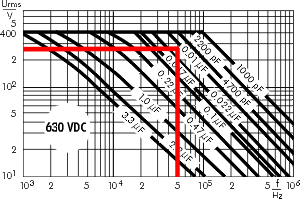
For the WIMA MKP 10 / 0.01µF / 630VDC/400VAC, for
example, this shows - when f = 50kHz - a permissible AC
voltage of
Urms = 280
V (graph 2).
 |
|
Graph 2: Permissible AC voltage
in relation to frequency at 10°C
internal temperature rise
(general guide). |
The AC voltage given in
the diagrams can also be used to determine the maximum
effective current
|
